A voltage stabilizer is any device that holds the circuit voltage at a specified level. There are many different types of stabilizers, but integrated circuit (IC) stabilizers are the most common. For components that require a regulated power supply, you often need a voltage stabilizer. Below we introduce how to connect voltage stabilizer to main line?
Cables and Terminations
Before any connections can be made, the incoming and outgoing cable sizes have to be selected and, on 200A units and above, the appropriate ring terminals fitted. (See Table 1). Cable size may be selected using values of current given in table 1 bearing in mind the usual limiting factors such as volt drop, heating, etc. The appropriate breaker sizes are also given. Note that the input and output currents can differ by 40%. This means that a larger cable size may have to be employed on the input than the output.
| Output (Amps/ph) | kVA (415V) | Input A (Max) | Input MCCB | Output MCCB | Ring Size (mm) |
| 10 | 7.2 | 14 | 16 | 10 | 8 |
| 20 | 14 | 28 | 32 | 20 | 8 |
| 30 | 21 | 41 | 50 | 32 | 8 |
| 50 | 36 | 69 | 80 | 50 | 8 |
| 75 | 54 | 103 | 100 | 80 | 8 |
| 100 | 72 | 138 | 160 | 100 | 8 |
| 150 | 108 | 207 | 200 | 160 | 80 |
Circuit Breakers
The recommended input and output breaker ratings are given in table 1. Values not shown may be interpolated. Due to the fact that breaker ratings jump in large steps, it is strongly recommended that adjustable trip level MCCBs are used. In this way, a high degree of protection may be achieved. The input MCCB should be of a type suited for use with inductive loads (with a high initial surge current). The output breaker should be chosen to suit the nature of the load.
Incoming Connections
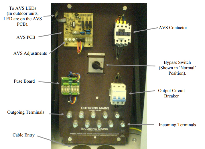
The three incoming lines should be connected to the terminals marked R1 S2 T3 on the terminal panel in the section marked INCOMING MAINS. The incoming neutral (if present) is connected to the N terminal and the system earth is connected to the E terminal. Care should be taken to ensure that all terminals are securely tightened. See photo 1.1. Note – cable access is from below to the rear on indoor units and via a gland plate at the bottom right on outdoor units.

Outgoing Connections
The three outgoing lines should be connected to the terminals marked R1 S2 T3 on the terminal panel in the section marked OUTGOING MAINS. The outgoing neutral should be connected to the N terminal and the load earth to the E terminal. N.B. The outgoing neutral cable should be fully rated. Care should be taken to ensure that all terminals are securely tightened. See photo 1.1. Ensure phase rotation continuity from input to output.
Earth/Neutral Connections
The Incoming and outgoing earth terminals of the voltage stabilizers are connected together and connected to the metal chassis work of the voltage stabilizer. In the interests of safety, they must be connected to a good quality, low impedance site earth point. The customer should also note that, due to the isolating nature of these voltage stabilizers, the output phase and neutral connections are floating with respect to earth. Depending on the site electrical arrangement, it may therefore be required to connect the output neutral terminal to the earth terminal to reference the load supply to site earth.
Rear Panel Layout
Photo 1.2 shows a typical layout of the terminal board. This is very similar in both indoor and outdoor units, except for the cable entry points.

Front Door Layout
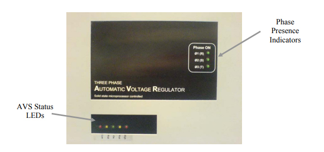
On the indoor unit, the voltage stabilizer status indicators are situated on the front door, a set of five LEDs. See photo 1.3. The phase present indicators are to the right of the upper panel also shown in the photograph below. On the outdoor unit, the voltage stabilizer indicator LEDs are inside the case on the voltage stabilizer PCB, on the terminal panel. The phase presence indicators are also on the inside, on the ST221/165 power PCBs.

