Static Voltage Stabilizer Basic
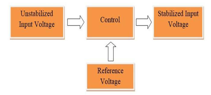
Voltage stabilizers can be broadly categorized as AC voltage stabilizers, DC voltage stabilizers, and automatic voltage stabilizers. This paper deals with static voltage, an ac voltage stabilizer. The most used stabilizer is a servo stabilizer and has many limitations in accordance with a static voltage stabilizer.
The forgoing stage of voltage stabilizer used in industries or for households is servo voltage stabilizer. Commercially the approved range of their operation is 150V-240V or 90V-280V. The lately introduced technology which excludes this old-fangled, low voltage, high correction time, high maintenance issues of servo stabilizer is static voltage stabilizer (SVS). Static voltage stabilizer doesn’t include any moving parts as in servo voltage stabilizer. The voltage in SVS is produced with the assistance of electronic circuits also it has absolute electronics to achieve correction in voltages and time. Therefore, it has an extremely high voltage correction speed than the servo voltage stabilizer.

Static Voltage Stabilizer Working Principle
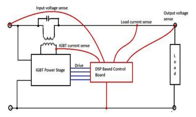
The static voltage stabilizers proffer improvement on the slow servo-controlled stabilizers. The basic study of SVR is with a buck-boost transformer with a high primary to the secondary ratio for voltage correction of 25%. The control voltage which is fed by the IGBT drives of SVS is given to the primary and input voltage is imposed to the secondary of the buck-boost transformer. The regulation of voltage with help of buck and boost is attained electronically without any step changes in the voltage at the time when the system regulates. This task is proficient through feedback and a control system implemented by using a TMS320F28069 microcontroller. The system uses IGBTs as power switches, direct AC-AC converter circuit improves the overall system response and fast voltage correction. Also, 12.8 kHz ePWM control operation using high-end Piccolo F28069 control card to achieve correction time of 20 to 30 millisecond.
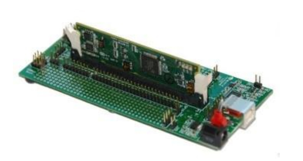
Static Voltage Stabilizer is implemented on Piccolo F28069 DSP-based board. This control board continuously senses input voltage, output voltage, load current, and IGBT current with help of CTs and VTs. Based on these values Piccolo F28069 DSP control board will trigger IGBT Bridge to produce voltage at its output with help of the PWM method.

Major Components of Static Voltage Stabilizer
- Buck Boost Transformer: Secondary of buck and boost transformer is connected input and output terminal of voltage stabilizer. Neutral between input and output of static voltage stabilizer is common hence voltage induced across secondary of the buck-boost transformer can add or subtract with input voltage. The primary buck-boost transformer is connected to the IGBT power stage.
- IGBT Power Stage: It consists of IGBT Bridge which is connected to the Piccolo F28069 DSP controller. The IGBT power stage is responsible for the generation of an appropriate amount of voltage with help of the PWM method. The output of the IGBT power stage is fed to the primary as it is the control circuit of the device. As the output of the IGBTs is fed to the primary of the transformer, it can be in phase or 180 degrees out of phase with the input line voltages. So the voltage induced across the secondary of Buck-Boost Transformer can be added or subtracted as per the required voltage needed at the load.
- DSP-based Control board: The major work of the DSP-based control board is to give PWM to drive the IGBT. It incessantly senses the value of input voltage, output voltage, load current, and IGBT current with help of a current transformer and voltage transformer connected to it. And this processed information as in feedback gives a signal to the IGBT power stage to generate desired voltage and duty cycle with help of the PWM method.

